trigger system
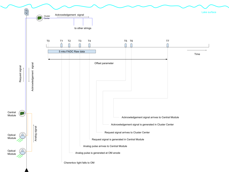
Raw data are produced by trigger system of the detector and composed by Data acquisition system (DAQ). The main element of the trigger system is a section. The section consists of 12 OM that are connected to section master module (SMM). Analog signals from Optical Modules are digitized in 12 channel 12 bit 200 MHz Flash ADC board (FADC) that are located in SMM. When digitized, the signal is transferred into the Xilinx Spartan 6 field programmable gate array (FPGA). The local trigger system was realized in the FPGA. It considers integrated over 1-8 bins digitized signals from all 12 channels. There are low and high amplitude thresholds. If the integrated signal is greater than low threshold, 120 ns window is opened to analyze what type of this excess low or high. This analysis is done for all 12 channels independently. After that channel request signal is formed with low or high flag. There is a coincidence matrix that is filled by request signals from all 12 channels. All requests are summed over time window (usually 100 ns) in the matrix in appropriate way. If this sum is greater than matrix parameter then section trigger request signal is sent to Cluster Center (CC) through 1 km line and request counter in SMM is incremented to 1. While received, CC generates acknowledgement signal to all sections in the cluster. When SMM is caught the signal, acknowledgement counter is incremented, timestamp is defined and SMM starts to form data. SMM reads values of request and acknowledgement counters, timestamp. And it goes in the past in 30mks buffer to time interval that defined by offset parameter to extract signals in 5 mks window (FADC tracks). All 12 FADC tracks are filtered by built-in algorithm which get rid of empty bins.
