The basic measuring units of the BAIKAL-GVD are optical modules, which are design to convert the Cherenkov radiation of muons and showers into electric signals. An OM consists of the following elements: a photo-multiplier tube (PMT), a controller, an amplifier, LED calibration unit, and a high-voltage converter. The OM block scheme is shown in Fig.1.

Photomultiplier tube

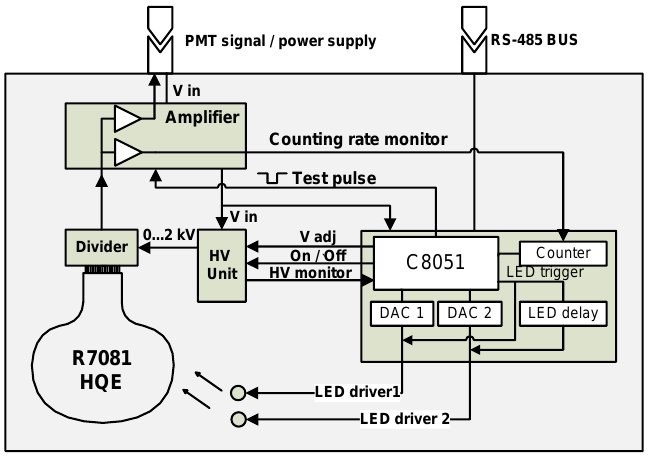
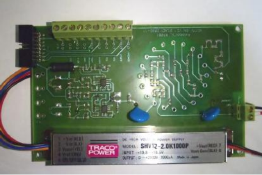
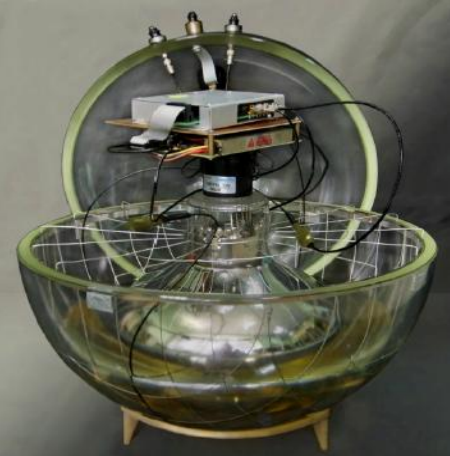
The choice of the optimal type of photomultiplier tube for the BAIKAL-GVD is a top priority task. The main requirements to PMT are high time resolution (at a level of several nanoseconds), large photocathode area, and high quantum efficiency. Currently, only Hamamatsu-R8055 and Hamamatsu-R7081HQE PMTs with hemispherical photocathodes satisfy the requirements of the BAIKAL-GVD experiment. PMTs R8055 and R7081HQE have, respectively, the following characteristics: the photocathode area ~1000 cm2 and ~500 cm 2 and the quantum efficiency ~0.2 and more than 0.3. PMTs of both types were tested as components of engineering arrays in Lake Baikal. At present R7081HQE is chosen as a light sensor of the BAIKAL-GVD (see Fig 1). The photomultiplier is fed by a high-voltage TRACO POWER SHV12-2.0K1000P DC/DC converter through a voltage divider with a resistance of 18 MΩ. Working voltage from the range 1300 – 1800 V is selected to provide a gain of the dynode PMT system of ~10^7. To provide reliable operation of the spectrometric channels of the telescope, the PMT signal is additionally amplified by a factor of 12 (the first amplifier channel). This amplification level provides both a sufficiently high average single-electron PMT signal (30-40 mV) with respect to the noise pulse amplitude in the spectrometric channel and the necessary range of linearity up to 100 photoelectrons (p.e.). Two-channel amplifier unit and PMT voltage divider are placed on the same board. The first amplifier channel is used for spectrometric measurements and the second channel (amplification factor 25) serves to amplify signals arriving at the noise pulse counter of the photomultiplier. The amplifier/divider board is shown in Fig. 2.

Controller

The optical module is controlled through a deep underwater bus RS-485 with the aid of a controller specially developed for BAIKAL-GVD based on a C8051F124 processor (see Fig. 3). The main functions of the controller are as follows: • adjustment of the PMT high voltage; • amplitude and time calibration of channels using LED light sources; • monitoring the basic parameters of the PMTs and electronics during long-term operation. The working PMT voltage is set using the control input of SHV12-2.0K1000P DC/DC converter. The control voltage is formed by a digital-to-analog converter (DAC) of the controller in the range of 0 – 2.5 V with a step of ~1 mV. As a result, the working PMT voltage can be set with an accuracy of about ~0.5%. The amplitude and time calibrations of the photomultiplier were performed using two Kingbright L7113 РВС-A LEDs. The LED brightness is highest at a wavelength of 445 nm, and the light pulse duration is about 5 ns. The controller provides precise control of the LED intensity and adjusts the delay between their signals. The LED intensity varies from 1 to ~10^8 photons per flash. Delay time between two LED’s pulses may be varied in the range up to 1000 ns with the step of 100 ns and the precision better than 1 ns. The effect of mutual influence of two LED does not exceed 0.5%.
The control of the PMT and OM electronics operation implies continuous monitoring of their main parameters and operation conditions. The controlled PMT parameters are the high voltage value, the phototube transit time, and the rate of PMT intrinsic noise. To inspect the high voltage, the PMT divider is equipped with a monitor output, the voltage at which is proportional to the total voltage across the divider. This voltage is measured by an analog-to-digital converter (ADC) of the OM controller. The technique of monitoring the PMT transit time is based on measuring the time interval between the LED triggering signal and the LED signal detected by the PMT. In mode of measuring PMT transit time the signal coinciding in time with the triggering signal is applied to the output cascade of the amplifier in the OM spectrometric channel. As a result, two signals are formed and the time between them is determined by the PMT transit time. This time interval is measured on the central module (CEM) of the section with an accuracy of about 2 ns. Note that the possibility of forced signal formation at the OM output is also used to monitor the operating performance of the section as a whole, without applying a high voltage across photomultipliers. The PMT intrinsic noise rate is measured using the second channel of the amplifier (with a gain ~25), the signal from which is provided to the pulse counter of the OM controller (Fig. 4). The width of time window for noise rate measurement can be set in the range from several milliseconds to 10 s, depending on the PMT operation mode. The counter detection threshold can be controlled from 0.2 up to 100 p.e.: the lowest operating threshold is limited by the noise level of the OM electronics. To monitor the external conditions of OM electronics operation, the controller allows one to measure the temperature and power supply voltages. A power supply voltage of 12 V is fed to the optical module through the same wire through which the PMT signal is transferred. The aggregation of power supply with the spectrometric channel simplifies significantly the system of deep underwater cable communications of BAIKAL-GVD section. However, this configuration increases the noise in the spectrometric channel to 10-15 mV because of the power supply unit intrinsic noise. The OM current consumption at a voltage of 12 V is 200 mA; the controller contribution is ~80 mA.

Design of optical module

The optical module design is shown in Fig. 4. The OM electronic components are placed in a pressure-resistant VITROVEX glass sphere 42 cm in diameter, which consists of two hemispheres. To fix reliably the hemispheres, the optical module is evacuated to a pressure of about 0.7 atm. The photomultiplier is glued into one of the hemispheres using silicon elastic gel, which provides an optical contact between the PMT and the sphere glasses. To reduce the influence of the terrestrial magnetic field, the PMT photocathode is enclosed in a mu-metal wire cage. The controller, amplifier, and high-voltage converter are mounted on the PMT base. Drivers equipped with LEDs are connected to the OM controller through high-frequency SMA connectors. The light from LEDs arrives at the center of the PMT photocathode through optical fibers 0.5 m long. The amplified PMT signal is extracted from the module through a deep underwater coaxial connector CP-50-862/8bЗ. The OM power supply is fed through the same connector. The slow control bus RS-485 is also led into the OM through the CP-50-862/8bЗ connector. A vacuum valve is placed on the sphere near the two connectors, and a manometer is connected to it for monitoring the pressure in the OM.

Angular sensitivity of OM

The information about the angular dependence of the optical module response to
Cherenkov radiation is of primary importance for simulating the processes of muon
and shower detection in the BAIKAL-GVD. The angular sensitivities were measured
for selected OM samples using a diffuse light source with a wavelength of 445 nm,
mounted at a distance of 2.5 m from the optical module. The optical module under
study was placed in a water-filled tank. Figure 5 presents the results of measuring
the angular sensitivities of OMs based on PMT R8055, ХР1807 (Photonis), and
R7081HQE.

logo-gvd